Digispark ATTINY85 Software Serial RX/TX
Contents
- Experiment Goals
- Software Serial
- FTDI Adapter
- Connecting the Circuit
- Plan the Program
- Building the Firmware
- Build the Driver Program
- Resources
| Difficulty Level | Beginner |
Note: This documentation is for programming the Digispark with
avr-gccandMakefilesdirectly, not with the Arduino IDE.
Note: P3 and P4 are overloaded for use via the USB emulation, and so programs that use P3 and P4 (for example, my Serial experiment) will cause some challenges with programming the board. You may need to disconnect P3 and P4 prior to programming, and if this is on a permanent circuit you probably will want a disconnect.
Today I'm going to document the next simple project with the Digispark ATTINY85: serial communication. If you're interested in the previous installments:
Experiment Goals
The goals for this experiment are pretty basic:
- Learn how to communicate with the Digispark ATTINY85 via Serial.
- Use FTDI USB to Serial.
- Use
avr-gccdirectly -- no Arduino tools or libraries. - Send a stream of bytes from a Python program running on the computer.
- Echo the bytes back from the microcontroller.
- Bonus points: flash an LED that indicates we're receiving data.
Software Serial
The Digispark doesn't include UART hardware support for serial communication, but we can still support serial RX/TX via software. If you've spent much time with Arduino, you'll be familiar with the Serial Monitor, and will probably miss it on the Digispark. If you're using the Arduino IDE with the Digispark, there are numerous tutorials about using the Arduino SoftwareSerial library, but the whole concept of these articles is to document programming the Digispark without Arduino. I didn't find many posts explaining the process, but hopefully this will help the few people who need this information.
This particular post will feature the https://github.com/shimniok/ATtinySoftSerial library. It doesn't come with many instructions, so I'll provide some extra commentary.
You will need a Digispark ATTiny85 development board with a recent version of the Micronucleus bootloader installed. You can follow this article for help with that step. My Digispark is a cheap clone, and pin 5 is set as RESET and not I/O (although it shouldn't matter). You will also need a USB to Serial adapter (or serial port and cable if you're old school) — I'm using an inexpensive FTDI adapter that I got from Ebay for a couple of bucks and it works great.
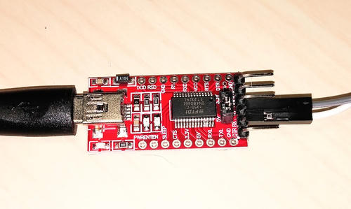
FTDI Adapter
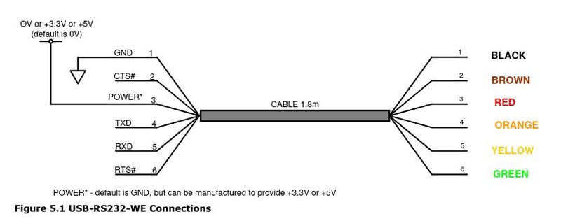
I'm going to spend a paragraph or two discussing the FTDI USB to Serial adapter. Yours may vary slightly, so be sure to check the pinout for your device. Mine is like this:
  - GND  1   Ground
  - CTS  2   Clear to Send/Handshake/Input)
  - VCC  3   +3.3V or +5V
  - TXD  4   Transmit
  - RXD  5   Receive
  - DTR  6   Request to Send/Output)
Of these we're only going to use digital pins #4 and #5 for this experiment. (TODO: extra follow-up on this in a deep dive on serial comms).
Connecting the Circuit
The software serial library we'll be using for this article uses pins 3 (RX) and 4 (TX) on the Digispark. If you're curious, you can find these values in SoftwareSerial.h:
#define RXPIN	   PB3
#define TXPIN	   PB4
Always a gotcha with serial comms, be sure to connect TX -> RX and RX -> TX. We're so used to connecting like/like that it's easy to forget (a classic mistake I made while wiring this up the first time).
  FTDI					    Digispark
  - TXD	  -----------------   - P3 (RX)
  - RXD	  -----------------   - P4 (TX)
Plan the Program
Before we start writing code, let's pause for a minute to think about what we want the program to do. One of our goals for the project is to send bytes from the computer and receive them on the microcontroller. We want to know what we received, and the easiest way to do that is to send those bytes right back over the wire!
So we want a simple serial echo, which is sort of the "hello world" program for serial. Luckily, the software library we're using has one example and that's exactly what it does.
But it would also be nice to have a visual indicator that we're receiving data, so we'll want to flash the onboard LED as well.
Our program in pseudocode will probably look something like this:
# pseudocode
loop forever:
	if receiving_data():
		bytes = rx_data()
		if flashing_interval:
			toggle_led()
		tx_data(bytes)
		pause()
	else:
		turn_off_led()
This is probably pretty close to what we need. One note: if we're looping to get the data, then we can't toggle the LED each loop or it will be too fast to see. So flashing_interval in the pseudocode above is a placeholder for this concept, and we'll flesh it out when we write the actual code.
Building the Firmware
Now that we've sketched the outline of what we want our (simple) program to do, let's write the code. You can find the finished program here:
https://github.com/matthew-macgregor/digispark-attiny85-experiments/tree/main/3-serial
We will start with the outline provided in the TinySoftSerial library and expand it to handle flashing the LED. Here's an annotated example:
#include <avr/io.h>
#include <util/delay.h>
#include "SoftwareSerial.h"

#define BLOCK_SIZE 12
// In my testing, 38400 works.
#define BAUD_RATE 38400

// incoming buffer
volatile char *inbuf[32];
// outgoing buffer
volatile char *outbuf[32];

int main()
{
	// PB1 is the builtin LED on newer Digispark clones. On older
	// models it was PB0.
	DDRB 	|= 	(1 << PB1);	// Set pin to output

	// Initialize the serial library
	softSerialBegin(BAUD_RATE);

	// Loop forever, but we'll use the loop variable to keep track
	// of when to flash the LED.
	for (int i = 0;; i++) {
		// There are bytes available on the wire
		if (softSerialAvailable()) {
			int c = softSerialRead();
			// Every BLOCK_SIZE RX/TX cycles, flash the onboard LED
			if (i % BLOCK_SIZE == 0) {
				PORTB 	^= 	(1 << PB1);
			}
			_delay_ms(10);
			// Echo the data back to sender
			softSerialWrite(c);
		} else {
			// Turn off the LED
			PORTB &= ~(1 << PB1);
			i = 0;
		}
	}
}
To build the hex and upload: make flash.
Notes for New Programmers
(Skip if you already know this stuff!)
If you're new to programming in C with microcontrollers there are a few things that might look confusing in the code above.
if (i % BLOCK_SIZE == 0) {
The modulus operator % calculates the remainder of i / BLOCK_SIZE. When
modulo is 0, i is evenly divisible by BLOCK_SIZE (the remainder is 0).
This is a useful idiom for "run this code but only once every few loops".
// Toggle a bit from 0 => 1 or 1 => 0
PORTB 	^= 	(1 << PB1);
The code above is using XOR (^) to toggle a bit. XOR sets the bit to 1 only
if the operands are different: 0b0101 ^ 0b1010 == 0b1111.
// Clear a bit
PORTB &= ~(1 << PB1);
~ is the Binary One's Complement operator, and it flips the bits. We can use
it to do something clever to clear a bit (set it to zero). It can be hard to
visualize, so here it is step-by-step:
  ;; (1 << PB1) Shift a 1 into the first bit
  0b00000010
  ;; ~ Flip the bits
  0b11111101
  ;; & AND with the bits in PORTB, only 1's in both operands will stay
& 0b00100010
  ----------
  ;; = Assign the result to PORTB, clearing the bit
  0b00100000
Build the Driver Program
After you've flashed the hex to your Digispark, software serial will be listening for input on the microcontroller, but you're not yet sending any data. Next we will build a simple Python program to provide some input. We'll use the popular pyserial library because it's dead simple to get up and running.
For this part of the project you will need Python 3.6+. We will set up a virtual environment to install the dependencies. I'm not going to go into detail on that part (I will in a future article). Just follow the instructions if you're not sure about what's going on.
There's a folder in the 3-serial example called serial-comm. Open that folder in a terminal.
Next, install a Python virtual environment:
python3 -m venv .pyenv
. .pyenv/bin/activate	# Linux / MacOS -- Windows is slightly different
pip install -r requirements.txt
Assuming those commands completed successfully, you can now run:
python serial-comm.py
You should see the light start flashing on your Digispark (and on the FTDI board) and text should start spitting out to your console:
b'TX >> hello echoed from the Digispark!'
b'TX >> hello echoed from the Digispark! \x01'
b'TX >> hello echoed from the Digispark! \x02'
In the simplified example below, the code is just opening a port for serial communication at a particular baud rate, writing some bytes to the wire, and reading in the response echoed from the board.
After plugging in the Digispark, I found the device by running ls /dev/tty* | grep USB. lsusb also provides useful information.
/dev/ttyUSB0: This is how my FTDI adapter shows up on Linux. This will be different for you depending on your OS.38400: Baud rate. If you changed this in your program for the Digispark you'll need to update this value.
More details can be found in the pyserial documentation.
import serial

with serial.Serial('/dev/ttyUSB0', 38400, timeout=1) as ser:
    ser.write(b'TX >> Hello World')
	rx = b''
	while True:
        x = ser.read(1)
		rx += x
		if x == b'':
			print(rx)
			rx = b''
I'll save a detailed explanation of the Python code for a future post. With any luck, you've now got software serial working with your Digispark!