A Lesson: Always Check Your Pinout
vs.
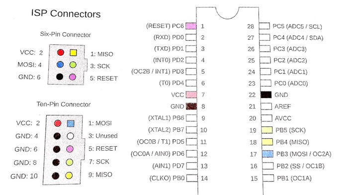
VCC - - MOSI VCC - - MOSI
RXD - - NC GND* - - NC
TXD - - RST GND - - RST
GND - - SCK GND - - SCK
GND - - MISO GND - - MISO
* I used this pin for GND
This is a story of two USBASP programmers. Cheap clone units from Ebay in the $2-$7 range. The first I bought a few years ago and it's worked handily for me, except that I noticed it seemed finicky with the ATTINY85 chips. In particular, VCC and GND didn't seem to work well when programming, but I could program successfully if I used an external power supply.
I followed the diagrams from a book, and really didn't put much thought into it, but when I started working with the Digispark boards I got curious and checked the voltage. I fully expected to see it shy of 5V, but my multimeter read 4.98-4.99V consistently, and my hypothesis was shot.
I got a second programmer for a couple of bucks off Ebay and gave it a test run. I noticed that the pinout was printed on the back of this one, and it was slightly different from how it labeled the GND pin. In particular, it showed that the pins directly beneath VCC were RXD, TXD not GND. This got me curious, and so I flipped over my original programmer and lo and behold, the pins were labeled there as well, following (mostly) the same pattern.
I'd been using the pin labelled RXD below as GND, because in the book the ten-pin connector diagram shows pins 4,6,8,10 are all GND. I assumed they were just interchangeable, and it never occurred to me to look on my board for something different. Silly, I know. Not the book's fault, I was just operating under the wrong assumption.
So I followed the pinout diagram from the programmer itself and, like magic, the fickle behavior promptly disappeared. The miracle of following directions!